How to Build a Servo Position Control System with PLC and Servo Drive?
Positioning control technology is an indispensable tool in the development of high-tech products. As a vital part of modern technology, it drives advancements in fields such as automated manufacturing, computing, and materials processing. This article will show you how to use a PLC and a servo drive to build a complete pulse-based servo motor position control system in position control mode, a classic industrial solution widely used in both professional automation and high-precision DIY & home automation projects.
- Components
- Working Principle
- Physical Setup
- Wiring Diagram
- Drive Configuration
- PLC Programming
- Conclusion
Components
Before you begin setting up the servo positio control system, please ensure you have the following components ready. We recommend checking off each item on the list before you start.
- PLC (High-Speed Pulse Output)
- Servo Drive (Compatible with pulse train input)
- Servo Motor (Equipped with an incremental encoder)
- Control Buttons (3-button pendant station x1, enable switch x1)
- Interposing Relays (x6)
All the components listed above are available from ATO online store. We offer recommendations on product selection and configuration, so please feel free to contact us.
Working Principle
The entire control system is based on a "pulse + direction" control scheme, and its operating principle can be broken down into the following steps:
- Command transmission: Buttons send commands to the PLC to control the servo’s enable, start, stop and direction.
- Pulse output: The PLC sends pulse signals to the servo drive. (pulse frequency defining speed, and total pulse count determining the final position.)
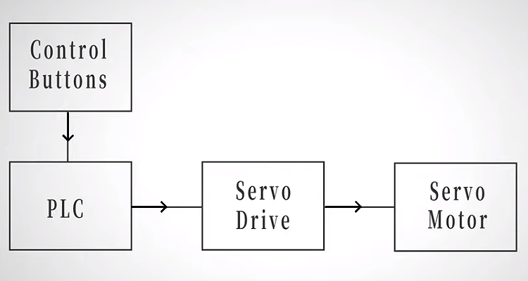
In this way, the PLC works in conjunction with the servo drive to achieve precise control over the motor's position and speed.
Physical Setup
With the control logic clearly defined, the next step is to bring the system into a real, physical environment. Proper hardware connections are essential, a clean and logical setup will help avoid signal interference and wiring errors.
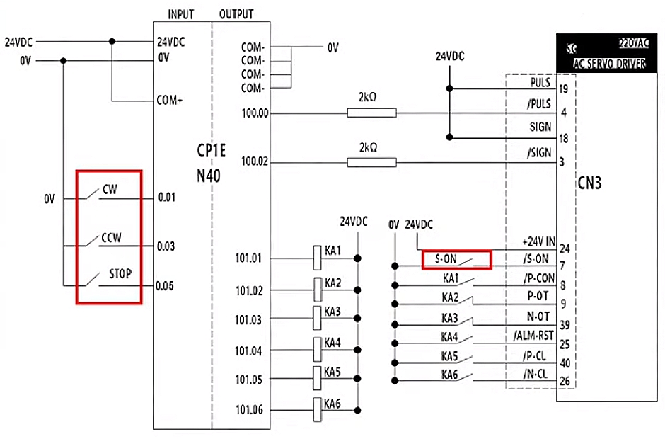
- Three-button pendant (CW, CCW, STOP) connects to PLC inputs 0.01, 0.03, and 0.05.
- S-ON button connects to terminal 7 of the drive's CN3 connector for direct servo enable control.
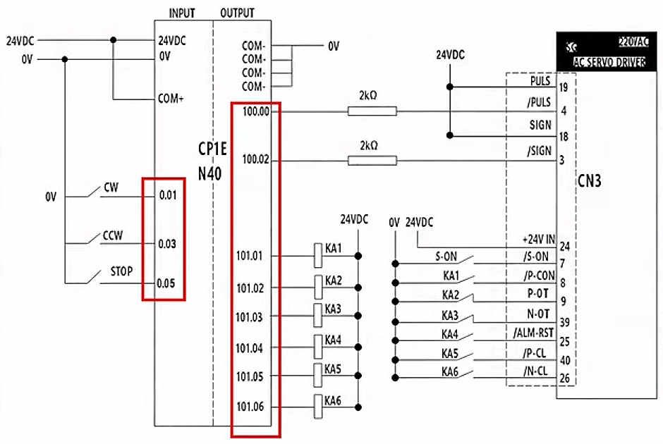
- PLC outputs pulse signals to the servo drive
- The drive controls the servo motor to rotate precisely according to the command
With these physical connections established, we can now take a closer look at how each signal is actually wired and mapped in detail.
Wiring Diagram
With the hardware in place, it's time to look closer at how the signals are actually wired between the PLC and the servo drive. A clear wiring diagram makes everything easier to understand and helps avoid mistakes during setup.
- This diagram clearly highlights the servo start/stop and enable circuits.
- This schematic also provides a detailed view of the PLC input and output wiring.
- The CN3 wiring table specifies the servo drive's control signal connections.
- Different wire colors correspond to different terminals and numbers.
- Six interposing relays, KA1 to KA6, are connected to interface the PLC and drive. They isolate the PLC from drive noise and allow flexible selection of different control methods when needed.
At this point, all control and signal connections are clearly defined, allowing us to move forward with drive configuration.
Drive Configuration
Before we start setting parameters, we need to initialize the servo drive. Don’t worry, it’s a straightforward process.
- Initialize the Drive
- Press M/SET on the drive, go to Fn005,
- Press DATA until 'P.Init' appears.
- Hold M/SET until 'donE' displays.
That’s your confirmation that initialization is complete. Finally, long-press DATA to return to the previous menu.
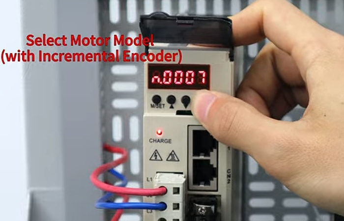
- Select the Motor Model
Now we’ll tell the drive which motor it's working with.
- Navigate to parameter PnOAO.
- Long press DATA, and enter the motor code for our incremental encoder motor (n.0007).
- Press M/SET to confirm.
- Set the Control Mode
- Navigate to Pn000.
- Press and hold DATA to edit.
- Set the second-to-last digit to '1'. This selects Position Control Mode.
- Press M/SET to confirm.
That's it! The drive is now ready to receive pulse signals from the PLC and control the motor position precisely.
PLC Programming
Now let's dive into the PLC programming. Start by creating a new project for your specific PLC model. The logic is simple and straightforward.
Here’s how it works:
- Press CW: The PLC outputs pulses at 20,000 Hz, and the motor rotates clockwise.
- Press CCW: The PLC still outputs pulses at the same frequency, but this time the motor rotates counter-clockwise.
- Press STOP : Pulse output stops immediately, and the motor comes to a halt.
That's the core logic, which is clean and simple.
Note: Remember those six interposing relays (KA1 to KA6) we wired up earlier? They provide isolation while supporting multiple control methods. Depending on your specific application needs, you can select the appropriate relay configuration.
With the programming complete, the system is now ready for a test run. If everything responds as expected with smooth starts, precise positioning, and immediate stops, you’ll know the setup is successful and the system is performing reliably.
Conclusion
In this article, we walked through how to build a complete servo position control system using a PLC and servo drive. By following these steps, you can achieve stable, precise, and responsive motor position control with a simple and practical pulse-based solution. For a more detailed and intuitive walkthrough, you can watch the step-by-step operation video below.
If you’re looking to build your own system, all the components covered in this guide are available in the ATO online store. We provide reliable products, clear documentation, and professional support to help you select the right configuration for your application, making your automation projects easier, faster, and more efficient.
