How to Set Up a Gas Detector Controller?
A gas detector controller serves as the central management unit of a fixed gas detection system, allowing users to configure connected gas detectors, manage alarms, record historical data, and monitor gas concentrations in real time.
This guide introduces the basic operation of the ATO gas detector controller, including menu navigation, 4-20mA output configuration, and historical data export. By following these procedures, users can quickly configure the controller, ensure reliable gas monitoring, and simplify routine maintenance.
I. Menu Navigation
The gas detector controller menu provides access to all configuration, monitoring, and maintenance functions. To enter the main menu, tap the Home icon on the control panel.
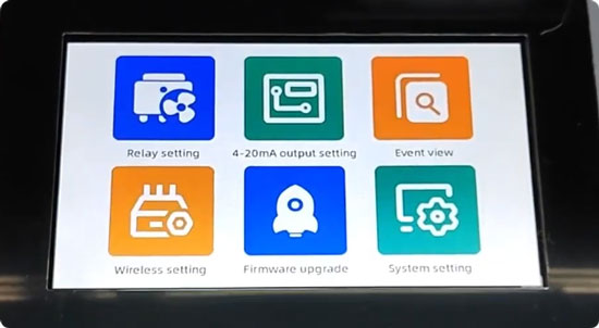
1. Relay and Output Settings
The Relay Setting menu is used to configure the alarm relay outputs for connected gas detectors. When an alarm is triggered, the relay outputs can activate external equipment such as warning lights, sirens, ventilation fans, or emergency shutdown systems.
For analog signal configuration, open 4-20mA Output Setting to view or adjust the output parameters. This menu allows you to verify that each gas channel is transmitting the correct 4-20mA signal to external PLCs, DCS systems, or other industrial automation equipment.
2. Communication and System Monitoring
The gas detector controller also provides several tools for system monitoring and communication management. Event View allows you to review historical alarm events and communication failures for easier troubleshooting. If wireless gas detectors are installed, configure the required communication parameters through Wireless Setting. To keep the controller operating reliably, use Firmware Upgrade to check the current firmware version or install available software updates, improving system stability, compatibility, and overall performance.
3. System Configuration
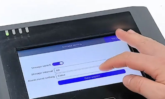
Most operating parameters are located under System Setting, where users can customize data logging, communication, and controller operation. Within this menu, Storage Setting allows you to configure the data logging interval and specify which alarm events are saved in the controller memory. Proper logging simplifies maintenance, troubleshooting, and compliance reporting. Additional system options include:
- Language: Select the preferred display language.
- Date & Time: Synchronize the controller clock to ensure accurate timestamps for alarms and historical records.
- Sample Setup: Configure the sampling interval according to application requirements.
- Delete History Data: Clear stored historical logs when memory needs to be released.
- Address Scan: Automatically detect and identify connected gas detectors on the communication network, reducing commissioning time.
- Reset Setting: Restore the controller to its factory default configuration when required.
Note: Performing a factory reset will erase all existing configuration settings. Record important parameters before restoring the controller to its default state.
After completing the required configuration, press the Home button to return to the monitoring screen.
II. 4-20mA Output Configuration
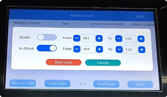
Proper 4-20mA output configuration ensures that the industrial gas detector controller accurately transmits gas concentration data to external PLC, DCS, or SCADA systems. To begin the configuration, open System Setting and select Address Scan, then tap Scan to access the scanning options. If the system uses only a 4-20mA gas channel, disable the RS485 option before tapping Start Scan. The gas detector controller will automatically scan the communication line for connected devices, and the detected device address will appear once the scan is complete. Return to the monitoring screen and press and hold the display to open the detailed configuration page for the detected address.
Configure the following parameters in sequence:
- Select the appropriate gas type.
- Choose the required measurement unit.
- Set the number of detection points assigned to the address.
- Define the measurement range according to the specifications of the connected gas detector.
- Configure the high and low alarm thresholds within the selected measurement range.
After completing the configuration, tap Settings to save all parameters. The 4-20mA gas channel is now ready for operation.
III. Historical Data Export
The controller supports exporting historical records to a USB flash drive, allowing operators to archive data or perform additional analysis on a computer. To export historical data:
- Tap Home to enter the main menu.
- Open System Setting.
- Select Storage Setting.
- Tap Data Export.
- Insert a USB flash drive into the USB port located on the controller PCB beneath the front cover.
- Wait for the controller to detect the USB device automatically.
- Start the export process and wait until it is completed.
- Safely remove the USB flash drive and transfer the exported files to a computer for record keeping, reporting, or further analysis.
IV. Conclusion
The gas detector controller provides centralized management for fixed gas detection systems by integrating detector communication, alarm management, 4-20mA analog output configuration, historical data logging, and USB data export into a single platform.
By following the procedures described in this guide, users can configure the controller efficiently, maintain accurate gas monitoring, and improve the reliability of daily operation and routine maintenance. For additional technical support on controller configuration, gas detector installation, or system integration, please contact the ATO.com for professional assistance.
