
How to Wire an Gas Detector Controller?
If you're installing an gas detector controller, this guide explains how to complete both the 3-wire 4-20mA analog output wiring and the 4-wire RS485 communication wiring. Whether you're connecting a single gas detector or integrating multiple detectors into a monitoring system, following the correct wiring procedure is essential for reliable operation and accurate gas monitoring.
The 4-20mA analog output allows the controller to receive continuous analog signals from connected gas sensors, making it suitable for standard industrial monitoring applications. RS485 digital communication, on the other hand, enables reliable long-distance networking with multiple detectors while providing stable data transmission and simplified system expansion. Before beginning installation, make sure the controller power is turned off and all wiring is completed in accordance with local electrical safety regulations.
3-Wire 4-20mA Analog Output Wiring
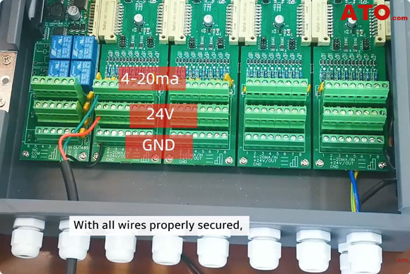
Begin by opening the front cover of the gas detector controller. Inside the enclosure, you will find the terminal blocks used for all wiring connections. Before making any connections, verify that the controller is powered off to prevent accidental short circuits or damage to the equipment.
Feed the 3-wire cable through the external cable gland, then tighten the gland securely after routing the cable. A properly tightened cable gland helps protect the controller against dust, moisture, and vibration while providing strain relief for the cable. Make the following connections:
- Green wire: 4-20mA Output terminal (analog signal line)
- Red wire: 24V terminal (positive power supply)
- Black wire: GND terminal (ground/common reference)
After completing the wiring, gently pull each conductor to confirm it is firmly secured in the terminal block. Loose connections may result in unstable current signals or intermittent communication with the controller. Once all wiring has been verified, close the controller cover before restoring power.
4-Wire RS485 Communication Wiring
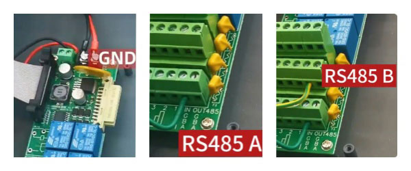
For RS485 communication, route the 4-wire cable through the external cable gland and tighten the gland securely to maintain the gas detector controller's environmental protection and cable stability. Make the following connections:
- Red wire: 24V terminal
- Black wire: GND terminal
- Green wire: RS485 A terminal (non-inverting data line)
- Yellow wire: RS485 B terminal (inverting data line)
The RS485 A and B lines enable stable and reliable long-distance digital communication between the controller and connected gas detectors. When connecting multiple detectors on the same RS485 network, ensure that the A terminal is connected to A and the B terminal is connected to B throughout the entire communication bus. Reversing these connections may prevent successful communication.
After completing the wiring, inspect all terminals to ensure they are secure and that no exposed conductors are touching adjacent terminals. Once the controller is powered on, verify that communication with the connected gas detectors is functioning normally before placing the system into service.
Conclusion
By following this wiring guide, you can correctly connect an gas detector controller using either the 3-wire 4–20 mA analog output or the 4-wire RS485 communication method. Proper wiring ensures accurate signal transmission, reliable power delivery, and stable communication between the controller and connected gas detectors, helping maintain dependable gas monitoring performance in industrial environments.
If the controller cannot communicate with the connected gas detectors after installation, verify the wiring sequence, terminal connections, power supply, and RS485 communication polarity before troubleshooting other system settings. For additional technical support, installation guidance or troubleshooting assistance, please visit the ATO.com. Our engineers are available to help you with installation, wiring, commissioning, and after-sales technical support.
