How to Test Current Transformer Polarity?
A current transformer (CT) is a fundamental device used in power systems and industrial automation for measurement, protection, and control. Current transformer polarity defines the directional relationship between the primary and secondary currents. If the polarity is incorrect, it can lead to reversed measurements, inaccurate fault current calculations, and even malfunction of protection systems such as relay misoperation or failure to trip. Because of this, verifying current transformer polarity is a critical step during installation and commissioning. In the following sections, we will introduce two reliable methods to test current transformer polarity: a simple DC method for quick field verification and a professional tester approach for more accurate and efficient testing.
I. DC Polarity Test
1. Components
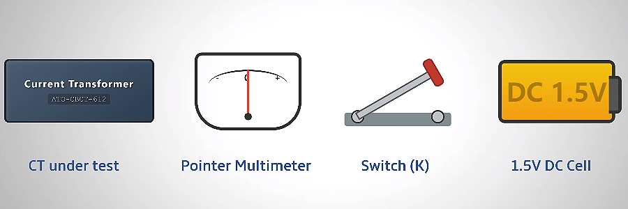
Before getting started, make sure the following items are ready:
- Current Transformer under test (x1)
- Pointer-type Analog Multimeter (x1)
- Switch K (x1)
- 1.5V DC cell (x1)
- Test leads and clips
Once everything is prepared, the next step is to understand how the test actually works.
2. Testing Principle
The DC polarity test is based on a simple transient electromagnetic effect inside the current transformer. When the switch is closed, a DC current pulse flows in the primary winding. This creates a transient magnetic flux in the CT core, inducing a momentary current in the secondary winding. The direction of this induced current is determined by the polarity relationship between the primary terminals (P1, P2) and the secondary terminals (S1, S2).
To visualize this, we usually connect an analog pointer meter. It appears as a brief deflection of the needle.
- Forward deflection → same polarity (additive polarity)
- Reverse deflection → opposite polarity (subtractive polarity)
3. Main Characteristics
In practice, this method stands out for its simplicity and convenience:
- Easy to perform
- Suitable for on-site use
- Ideal for quick verification during installation and maintenance
4. Test Procedure
Wiring
Getting the wiring right is key before carrying out the test.
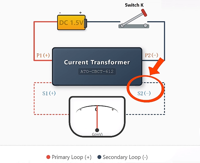
① The primary side
- Connect the battery POSITIVE to the current transformer's primary terminal P1.
- Connect the battery NEGATIVE to primary terminal P2.
- Place the knife switch in series on the primary side.
② The measurement side
Set your analog multimeter to its most sensitive DC millivolt range.
- Connect the meter’s POSITIVE (red) lead to secondary terminal S1.
- Connect the NEGATIVE (black) lead to secondary terminal S2.
Procedure
The current transformer polarity test is a brief, momentary check. Close the switch for a short instant and observe the pointer on the meter.
- If the needle swings clockwise (toward the positive side) when the switch is closed, the current transformer has subtractive polarity, confirming that P1 and S1 share the same polarity.
- If the needle swings counter-clockwise (toward the negative side), the current transformer has additive polarity, indicating that the polarity is reversed.
This simple observation provides a reliable way to verify current transformer polarity in the field.
II. Current Transformer Tester
1. Components
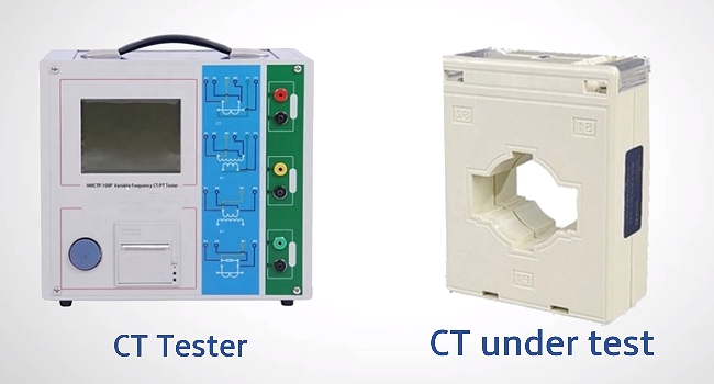
To use this method, you'll need:
- Current Transformer Tester
- Current Transformer under test
- Appropriate test cables and clamps
2. Testing Principle
Unlike the manual DC method, a dedicated current transformer tester automatically injects a known test signal into the transformer and then measures the primary‑to‑secondary phase relationship, ratio, and other parameters.
This method automates the entire procedure and generates a complete test report, reducing human error and enhancing test efficiency.
3. Main Characteristics
Building on this principle, the current transformer tester provides several key advantages:
- Fast and highly accurate
- Provides multiple key parameters at once / Provides detailed quantitative data
- Ideal for professional testing, commissioning, and routine verification
4. Test Procedure
Wiring
The setup process remains straightforward:
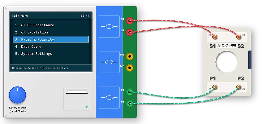
- Connect the tester’s high-current output to the current transformer primary terminals (P1, P2).
- Connect the measurement inputs to the secondary terminals (S1, S2).
- Select the "Ratio & Polarity Test" function on the tester.
- Power on the device and start the test.
Procedure
- The instrument will automatically complete the measurement, and the results will be displayed within a few seconds.
- If no alarm is indicated and the polarity is shown as "Subtractive", the current transformer polarity is correct.
The current transformer tester method is fast, accurate, and fully automated, providing comprehensive and traceable test results. It is well suited for commissioning, periodic inspection, and acceptance testing.
III. Conclusion
We've covered two reliable methods to test current transformer polarity: the simple DC method for quick field verification and the current transformer tester method for more accurate and automated analysis. Choosing the right approach depends on your testing requirements, from basic checks to professional commissioning.
For a more intuitive understanding, you can watch the demonstration in the video below. And if you’re looking for reliable current transformer testing equipment, feel free to explore the ATO online store for practical solutions that improve both efficiency and accuracy.
