
Remote Transmission Pressure Gauge vs. Electric-Contact Pressure Gauge
Pressure gauges do more than display pipeline pressure in an industrial system. Depending on their output signals, they can also support continuous pressure regulation or trigger equipment to start and stop at preset pressure limits. Remote transmission pressure gauges and electric-contact pressure gauges serve these two different purposes, although their similar appearance can make them easy to confuse.
The key to choosing between them lies in how they transmit pressure information and interact with control equipment. This article compares their structures, working principles, wiring, and control applications to help identify the right type for different pressure-control requirements.
- Appearance and Wiring Differences
- Working Principles and Signal Output
- Control Configurations and Operating Logic
- Key Differences
- How to Choose the Right Pressure Gauge
- Conclusion
I. Appearance and Wiring Differences
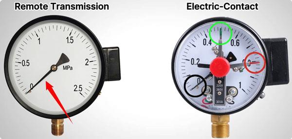
Remote transmission pressure gauges and electric-contact pressure gauges have a similar external appearance. Both typically use threaded process connections, such as G½ or M20×1.5, and may have three electrical wires. The main differences become apparent when examining their dial pointers and wiring functions.
A remote transmission pressure gauge usually has a single pointer that indicates the current pressure. An electric-contact pressure gauge has three pointers: one for pressure indication and two adjustable pointers for setting the upper and lower pressure limits.
Their wiring serves different purposes as well. The three wires of a remote transmission pressure gauge typically correspond to power, signal output, and common. For an electric-contact pressure gauge, the three connections are used for the upper-limit contact, lower-limit contact, and common terminal.
Although these two pressure gauges may look alike, their pointer arrangements and electrical connections reflect their different roles in pressure monitoring and control.
II. Working Principles and Signal Output
Although remote transmission pressure gauges and electric-contact pressure gauges both use a Bourdon tube to measure pressure, they convert pressure changes into different types of electrical outputs. One sends a continuous signal for pressure monitoring, while the other switches a circuit when the pressure pointer reaches a preset limit.
1. Remote Transmission Pressure Gauge: Analog Signal Output
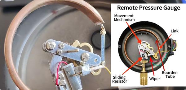
A remote transmission pressure gauge combines a Bourdon tube measuring mechanism with a sliding resistor, or potentiometer. As pressure changes, the Bourdon tube deforms, moving the pointer across the dial and driving a wiper along the wire-wound resistor.
The wiper's movement changes the resistance, generating a continuous analog output that corresponds to the measured pressure. This signal can be sent to a compatible PLC, VFD, or monitoring system for real-time pressure measurement and feedback control.
2. Electric-Contact Pressure Gauge: ON/OFF Switching Output
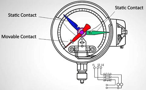
An electric-contact pressure gauge uses mechanical electrical contacts to trigger control actions at preset pressure limits. In addition to the main pointer, the dial has adjustable upper- and lower-limit pointers. As the measured pressure changes, the main pointer moves toward one of the preset limits. When it reaches the corresponding contact point, the contact mechanism changes the circuit state, opening or closing the electrical circuit according to the configured contact arrangement.
Unlike a remote transmission pressure gauge, this type does not continuously transmit the measured pressure value. Instead, it signals whether a preset pressure threshold has been reached, making it suitable for pump start/stop control and pressure alarms. The distinction between continuous analog output and ON/OFF switching determines how each gauge connects to a control system and what control functions it can perform.
III. Control Configurations and Operating Logic
The output signal determines how a pressure gauge interacts with the rest of a control system. A remote transmission pressure gauge supports continuous pressure regulation through a VFD or PLC, whereas an electric-contact pressure gauge typically triggers pump operation through a relay and contactor when the pressure reaches preset limits.
1. Remote Transmission Pressure Gauge: VFD/PLC Closed-Loop Control
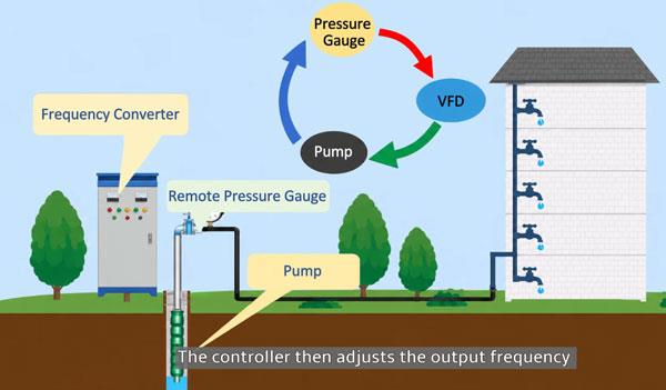
In a constant-pressure water supply system, a remote transmission pressure gauge sends real-time pressure data to a VFD or a PLC equipped with a compatible analog input. A typical setup uses a 4–20 mA signal, depending on the gauge model. The control process follows this sequence:
- Pressure measurement: The gauge monitors the pressure in the pipeline and converts it into an analog signal.
- Signal processing: The VFD or PLC receives the signal and compares the measured pressure with the target value.
- PID regulation: Based on the pressure difference, the controller calculates the required adjustment.
- Motor speed adjustment: The VFD changes the pump motor's operating frequency, regulating pump speed and water output to bring the pressure closer to the setpoint.
Because the motor speed adjusts according to demand, the system can maintain pressure within a narrower range without relying on frequent full-speed starts and stops. Under suitable operating conditions, this approach can reduce energy consumption and mechanical stress on the pump and motor.
- Key advantages:
More precise pressure regulation through continuous feedback.
Adjustable pump speed to accommodate changing water demand.
Reduced motor cycling and potential energy savings.
2. Electric-Contact Pressure Gauge: Relay and Contactor Start/Stop Control
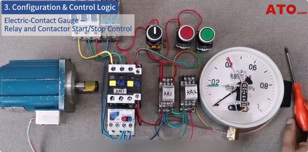
An electric-contact pressure gauge typically controls a pump through a relay and contactor. Instead of continuously adjusting motor speed, the system starts or stops the pump when the measured pressure reaches preset thresholds. For example, the upper pressure limit can be set to 0.50 and the lower limit to 0.30, using the same pressure unit for both values. The control sequence works as follows:
- Low-pressure detection: When the pressure drops below the lower limit, the lower-limit contact changes state and signals the control circuit to start the pump.
- Pump startup: The relay energizes the contactor, switching on the pump motor.
- Pressure buildup: The pump runs and raises the pipeline pressure.
- High-pressure detection: When the pressure reaches the upper limit, the upper-limit contact changes state, causing the relay and contactor to switch off the pump.
- Repeat cycle: As water demand reduces the pressure, the pump remains off until the lower limit is reached again.
The actual contact states depend on the gauge's contact configuration and control-circuit wiring, so the terminal diagram must be checked before installation.
This arrangement is straightforward and often requires fewer control components than a variable-speed system. However, pressure fluctuates between the two setpoints, and repeated motor starts and stops can increase mechanical wear and starting-current demand.
- Key advantages:
Simple wiring and control logic.
Lower initial system cost for basic applications.
Suitable for pump start/stop control and pressure-limit alarms where continuous regulation is unnecessary.
IV. Key Differences
Remote transmission pressure gauges send continuous pressure signals to a compatible control system, supporting pressure monitoring and variable-speed regulation. Electric-contact pressure gauges trigger switching actions at preset pressure limits, making them suitable for basic pump control and pressure alarms. The main differences between the two types are summarized below.
| Feature | Remote Transmission Gauge | Electric-Contact Gauge |
| Signal Type | Analog (continuous) | Switch (ON/OFF) |
| Control Precision | High (smooth PID regulation) | Low (interval start/stop) |
| Pressure Stability | Excellent (±1%) | Moderate (5–10% fluctuation) |
| System Cost | Higher (needs VFD/PLC) | Lower (relay + contactor only) |
| Best For | Precise supply, industrial process | Simple pump control, alarms |
V. How to Choose the Right Pressure Gauge
Choose a remote transmission pressure gauge if your system uses a compatible VFD or PLC and requires remote pressure monitoring, data recording, or real-time feedback control. An electric-contact pressure gauge is more suitable for automatically switching equipment or triggering alarms at preset pressure limits, especially in simple control systems.
In some applications, both pressure gauges can work together: the electric-contact pressure gauge handles local pressure-limit switching, while the remote transmission pressure gauge sends continuous pressure data to the control room. The right choice depends on your control requirements, signal compatibility, and system configuration.
VI. Conclusion
Remote transmission pressure gauges and electric-contact pressure gauges differ mainly in their electrical outputs and control functions. Remote transmission models support continuous pressure monitoring and feedback regulation, while electric-contact models trigger switching actions at preset pressure limits. Selecting the right type helps match the pressure measurement system to the required control strategy, whether the priority is stable pressure regulation, simple pump automation, or pressure alarm protection. Explore ATO.com for more insights into industrial automation systems and their control applications.
