
How to Add Overtravel Protection & Reset Alarms in PLC Servo Position Control?
In a servo positioning system, reliable motion control requires more than simply driving a motor. The system must also be able to detect over-travel conditions, stop motion before mechanical damage occurs, and provide a safe method for clearing alarms after faults are resolved.
This guide demonstrates how to upgrade a PLC pulse-controlled servo system by adding overtravel protection and alarm reset functionality using three interposing relays. The result is a safer and more robust servo position control system suitable for industrial applications.
- Components
- System Architecture
- Physical Wiring
- Servo Drive Configuration
- PLC Programming
- System Operation
- Fault Diagnosis
- Resetting Servo Alarms
- Conclusion
Components
- PLC with high-speed pulse outputs
- Servo drive
- Servo motor
- Three-button pendant station (CW, CCW, and STOP)
- S-ON enable button
- KA1 – Clockwise (CW) overtravel limit relay
- KA2 – Counterclockwise (CCW) overtravel limit relay
- KA3 – Servo alarm reset relay
I. System Architecture
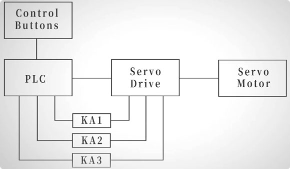
The system uses a standard pulse-and-direction control method. The PLC receives CW, CCW, and STOP commands from the pendant station and generates pulse signals to the servo drive, which controls the movement of the servo motor.
When the CW or CCW travel limit is reached, the corresponding relay is activated and sends a signal to the PLC to immediately stop pulse output, preventing further movement in that direction and helping protect the machine from mechanical damage. The servo alarm reset relay (KA3) allows the PLC to remotely reset the servo drive after the fault has been diagnosed and resolved.
II. Physical Wiring
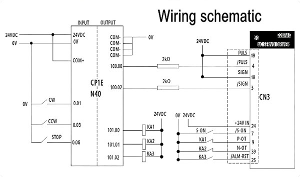
1. Pendant and Enable Wiring
The 3-button pendant is connected to the PLC inputs:
| Function | PLC Input |
| CW | X0.01 |
| CCW | X0.03 |
| STOP | X0.05 |
Wire the S-ON enable button directly to Pin 7 of the servo drive's CN3 signal connector. Pressing the button enables the servo drive and allows it to receive motion commands from the PLC. The PLC high-speed output terminals connect to the servo drive pulse input terminals, transmitting pulse and direction signals for position control.
2. PLC Pulse Output Wiring
The PLC high-speed output terminals send pulse and direction signals to the servo drive. These signals determine:
- Motor rotation direction
- Pulse frequency (speed)
- Positioning movement
3. CN3 Signal Connector Reference
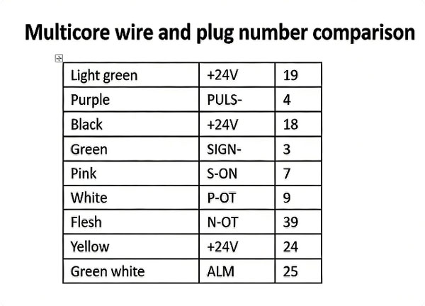
The multicore wire and plug number comparison table provides a quick reference for wiring the servo drive's CN3 signal connector. It identifies the wire color, signal name, and pin number for each conductor in the multicore cable, making it easier to terminate every wire on the correct terminal.
For example, Purple corresponds to the PULS− signal (Pin 4), Green to SIGN− (Pin 3), Pink to S-ON (Pin 7), White to P-OT (Pin 9), Flesh to N-OT (Pin 39), and Green/White to the ALM signal (Pin 25). The Light Green, Black, and Yellow wires are assigned to the +24V supply on Pins 19, 18, and 24, respectively. By matching the wire color with its corresponding signal and pin number, the CN3 connector can be wired accurately, ensuring reliable communication and control between the PLC and the servo drive.
4. Power and Motor Wiring
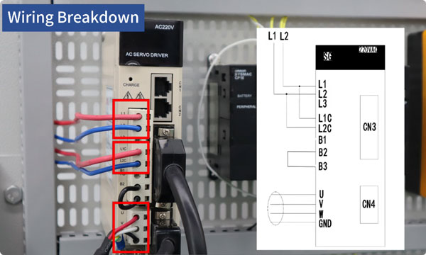
The servo drive requires separate connections for power, servo motor, signal, and encoder feedback to ensure stable operation and accurate position control. Connect the main power supply to terminals L1 and L2, and connect the control power supply to L1C and L2C. The servo motor power cables should be wired to terminals U, V, W, and GND.
The CN3 signal connector carries all control signals between the PLC and the servo drive, including pulse, direction, S-ON, positive and negative overtravel inputs, and the alarm reset signal. Finally, connect the encoder cable to the CN4 port. The encoder continuously feeds the motor position back to the servo drive, enabling accurate closed-loop position control and ensuring precise servo positioning.
5. Relay Wiring
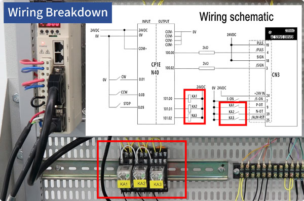
The final section of the wiring diagram shows the connections for the three interposing relays, which provide overtravel protection and remote alarm reset for the servo positioning system. The relays are assigned as KA1 for the clockwise (CW) limit, KA2 for the counterclockwise (CCW) limit, and KA3 for alarm reset.
During operation, if the mechanism reaches either travel limit, the corresponding limit relay is energized and immediately stops motion in that direction, preventing the axis from moving beyond its safe operating range. The KA3 relay is connected to the servo drive's /ALM-RST input. After the fault has been diagnosed and corrected, the PLC can momentarily energize KA3 to send an alarm reset signal to the drive, allowing the system to resume normal operation without manually resetting the drive.
III. Servo Drive Configuration
With the hardware setup complete, the next step is configuring the servo drive. We'll adjust the key parameters needed for reliable PLC control.
1. Initialize Servo Drive Parameters
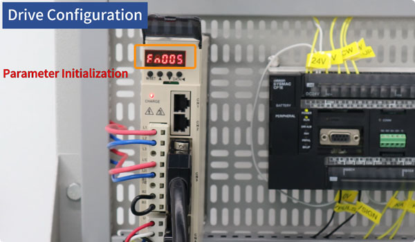
Before configuring the servo drive, initialize its parameters to restore the factory default settings. This ensures that any previous configurations are cleared and provides a consistent starting point for the new position control setup. To initialize the drive, press M/SET and navigate to Fn005.
Press DATA until P.Init appears, then press and hold M/SET until the display shows donE, indicating that the initialization has been completed. Finally, press and hold DATA to return to the main menu. Once the parameters have been reset, the servo drive is ready for the remaining configuration steps, including motor selection and position control mode settings.
2. Select the Correct Motor Code
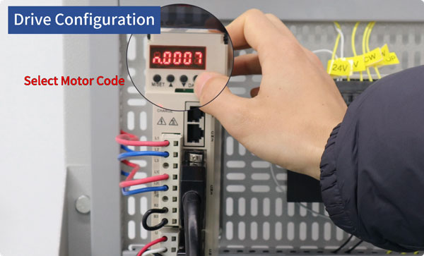
After initializing the servo drive, the next step is to configure the correct motor code. The selected motor code must match the connected servo motor to ensure proper communication and stable operation. Navigate to parameter Pn0A0, then press and hold DATA to enter the motor code setting menu. Enter the motor code that corresponds to your servo motor model.
For the incremental encoder motor used in this example, the correct setting is n.0007. Once the value has been entered, press M/SET to save the configuration. Selecting the correct motor code allows the servo drive to recognize the motor characteristics correctly, providing a solid foundation for accurate position control and reliable system performance.
IV. PLC Programming
With the servo drive configured, the next step is programming the PLC.
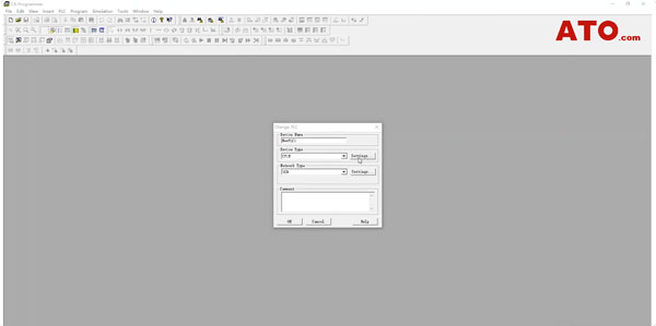
1. Create a New PLC Project
Open the PLC programming software and create a new project. Select CP1E as the device type. In the Device Type Settings window, set the CPU Type to N40, then click OK. The project is now configured for the CP1E-N40 PLC hardware.
2. Configure Pulse Output
The program uses the SPED (Speed Output) instruction to control the servo motor. This instruction sets the pulse output frequency and starts pulse generation directly, without acceleration or deceleration, making it suitable for basic positioning and motion control applications.
3. Build the Motion Control Logic
The ladder program is straightforward. When the CW push button is pressed, the PLC outputs pulses at 20,000 Hz, causing the servo motor to rotate clockwise. Pressing the CCW button sends pulses at the same frequency but in the reverse direction, driving the motor counterclockwise. Pressing the STOP button immediately stops pulse output, bringing the servo motor to a complete stop.
4. Add Overtravel Protection
To improve system safety, overtravel protection is added to the ladder logic. When the CW Limit relay (KA1) is activated, the PLC immediately blocks any clockwise motion to prevent the machine from moving beyond its allowable travel range. Likewise, when the CCW Limit relay (KA2) is triggered, all counterclockwise motion is disabled. An Alarm Reset relay (KA3) is also included in the program. It is controlled by a dedicated internal PLC bit and can be activated after the fault has been identified and corrected, allowing the servo drive to clear the alarm and resume normal operation.
V. System Operation
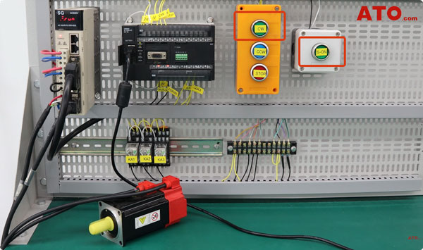
With both the hardware and PLC program ready, it's time to test the system and see how the overtravel protection works in practice. Press the S-ON button to enable the servo drive. Once the drive is enabled, the servo system is ready to operate. Next, press the CW button. The PLC begins sending pulse commands, causing the servo motor to rotate clockwise.
As the mechanism approaches its clockwise travel limit, the CW Limit relay (KA1) is activated. The servo drive immediately detects a Positive Over Travel (P-OT) condition and displays fault code d00. At the same time, motion is stopped automatically, preventing the mechanism from moving beyond its physical limit and protecting the machine from potential damage.
VI. Fault Diagnosis
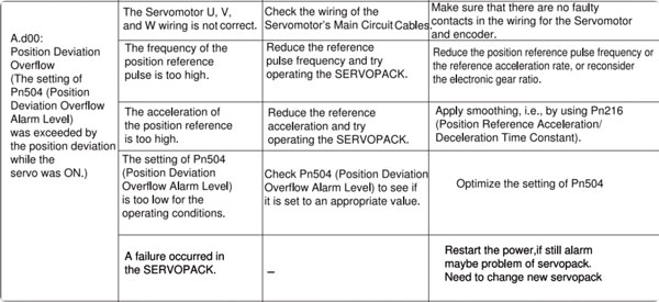
When the servo drive stops and displays fault code d00, the next step is identifying the cause of the alarm. According to the ATO servo drive manual, fault code d00 indicates Position Deviation Excess, meaning the difference between the commanded position and the actual motor position has exceeded the allowable limit defined by parameter Pn504.
The manual also provides a list of possible causes along with the corresponding corrective actions. Use this troubleshooting checklist to inspect the system step by step, eliminating each potential cause until the fault is identified. If the alarm remains after verifying the wiring, parameter settings, and other recommended checks, the servo drive itself may be defective and should be replaced.
VII. Resetting Servo Alarms
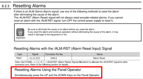
After the fault has been identified and corrected, the servo alarm can be cleared using one of two methods. The first method is to reset the alarm directly from the servo drive panel. Simply press the UP and DOWN buttons simultaneously on the operator panel to clear the alarm. Alternatively, you can reset the alarm by cycling the control power.
This method is particularly useful for certain encoder-related alarms that cannot be cleared using the panel controls alone. Before performing any reset, always make sure the root cause of the fault has been eliminated. Resetting an alarm without correcting the underlying problem can result in repeated faults, equipment damage, or even a fire hazard.
Conclusion
Adding overtravel protection and a reliable alarm reset function is an important step toward building a safer and more dependable PLC servo motor position control system. By combining proper hardware wiring, servo drive configuration, PLC programming, fault diagnosis, and correct alarm recovery procedures, you can effectively protect your equipment from mechanical overtravel while improving system reliability and reducing downtime.
If you have any questions about PLC servo motor control, servo drive parameter settings, wiring, troubleshooting, or product selection, feel free to contact the ATO.com. Our technical team is always ready to provide professional guidance and help you choose the right automation solution for your application.
