
How to Add Dual Emergency Stop in PLC Servo Control Systems?
Dual emergency stop is one of the important safety functions of servo motion control systems. It provides an extra protection layer for PLC-based servo motion systems, enabling emergency shutdown from two independent positions. Integrating hardware and PLC software emergency stop circuits to build two independent cut-off paths is a reliable solution. This article explains the full implementation workflow to improve machine safety and minimize equipment downtime.
- Why Use a Dual Emergency Stop?
- Required Components
- Working Principle
- Wiring Configuration
- Servo Drive Configuration
- PLC Control Logic
- System Verification
- Conclusion
I. Why Use a Dual Emergency Stop?
A dual emergency stop provides redundant protection, increases accessibility and improves response time. Once the emergency stop button is pressed, two independent protection mechanisms take effect simultaneously:
- Hardware Protection: The servo enable circuit is disconnected immediately.
- Software Protection: The PLC simultaneously stops pulse output.
Both actions occur at the same time, ensuring the motor stops even if one control path becomes unavailable. Now that we understand why dual protection matters, let’s gather the components needed to build this system.
II. Required Components
To build a dual emergency stop system, you will need the following components:
- PLC×1
- Servo Drive×1
- Servo Motor×1
- 3-Button Control Station×1
- S-ON Enable Button×1
- E-Stop Button×1
- Interposing Relays×3
All of these components are available at the ATO online store.
III. Working Principle
A standard PLC servo control system operates by sending pulse signals from the PLC to the servo drive, which controls motor movement. A dual emergency stop adds two independent shutdown paths to improve system safety.
- Hardware Protection: The E-Stop button disconnects the servo enable (S-ON) circuit, immediately disabling the servo drive.
- Software Protection: The same E-Stop signal is sent to the PLC, which instantly stops pulse output and prevents any further motion commands.
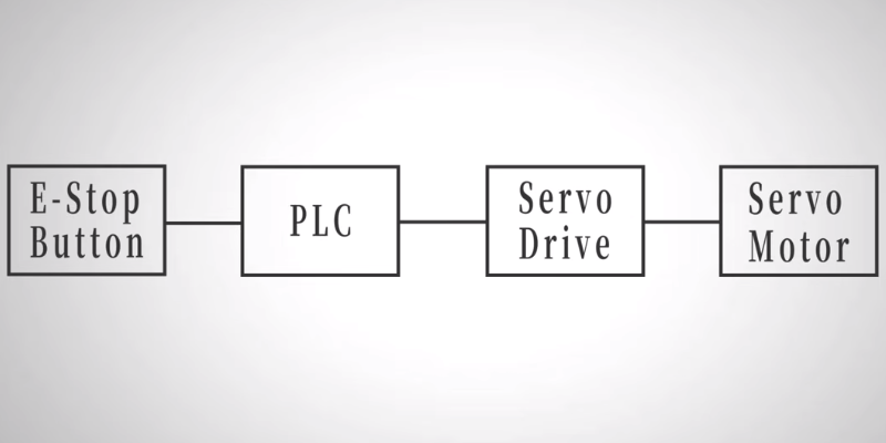
Because both protection paths operate independently, the servo system can still perform a safe shutdown even if one path becomes unavailable.
IV. Wiring Configuration
Correct wiring is essential for ensuring both reliable motion control and effective emergency stop protection. The dual emergency stop system integrates the PLC, servo drive, control buttons, and protection circuits into a coordinated control architecture.
1. Control Circuit Wiring
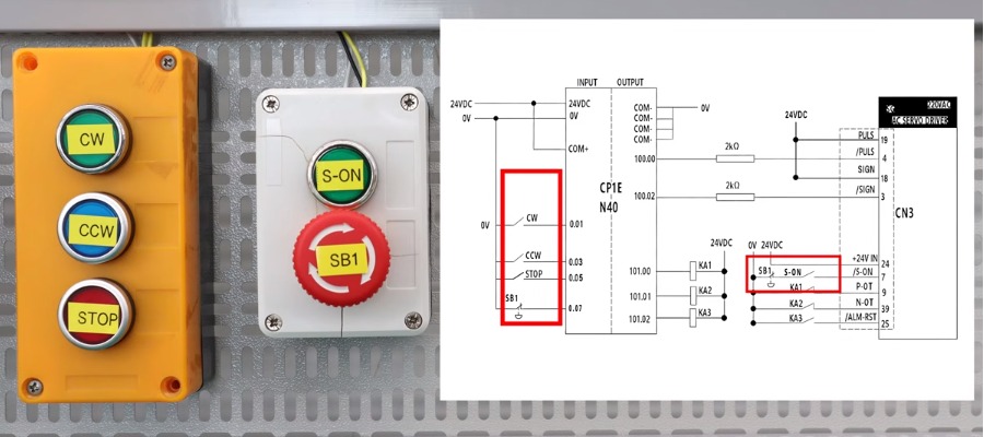
The clockwise (CW), counterclockwise (CCW), and STOP buttons are connected to dedicated PLC input terminals, allowing the PLC to accurately detect operator commands. The E-Stop button serves two functions simultaneously:
- Hardware protection: Wired in series with the servo enable (S-ON) circuit to immediately disable the servo drive.
- Software protection: Connected to a dedicated PLC input, allowing the PLC to instantly stop pulse output when an emergency stop is activated.
2. Servo Drive Wiring
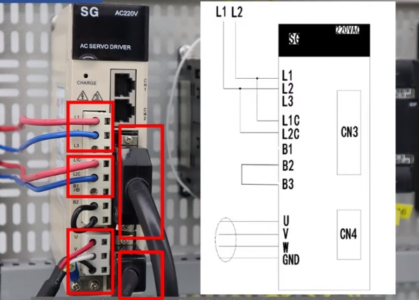
The servo enable (S-ON) signal is connected to Pin 7 of the CN3 connector on the servo drive. High-speed pulse and direction outputs from the PLC are wired to the corresponding control inputs on the drive, enabling precise position control.
The drive is powered through the main power terminals (L1/L2) and control power terminals (L1C/L2C). The motor is connected to the U, V, W, and ground terminals, while the encoder feedback cable connects to the CN4 interface for accurate position feedback.
3. Protection Circuit
Three interposing relays provide additional protection and fault handling:
- KA1: Clockwise travel limit protection
- KA2: Counterclockwise travel limit protection
- KA3: Servo alarm reset
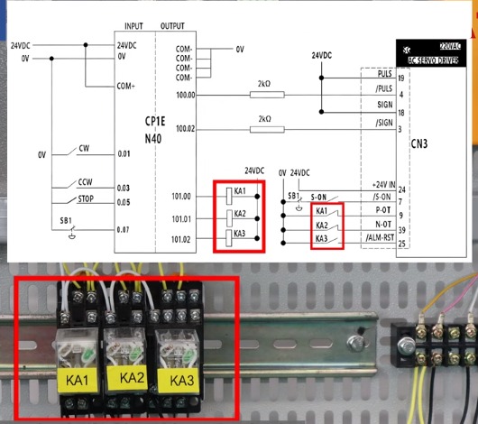
Together, these wiring connections create a reliable servo control system with redundant emergency stop protection, precise motion control, and dependable fault recovery.
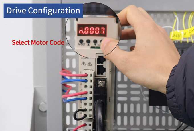
V. Servo Drive Configuration
After completing the wiring, configure the servo drive before operation.
- Initialize Parameters: Restore the drive to its default configuration before commissioning. This clears previous settings and prepares the drive for a new configuration.
- Select the Correct Motor Code: Choose the motor code that matches the connected servo motor. In this example, an incremental encoder motor uses Pn0A0 = n.0007. Selecting the correct motor code ensures proper communication between the servo drive and motor.
- Set Position Control Mode: Configure Pn000 to enable Position Control Mode, allowing the drive to receive pulse commands from the PLC.
After completing these three steps, the servo drive is ready for PLC pulse control.
VI. PLC Control Logic
The PLC ladder program controls motor motion through high-speed pulse outputs. The operating sequence is straightforward:
- CW: Rotate clockwise
- CCW: Rotate counterclockwise
- STOP: Controlled stop
- E-Stop: Immediate pulse shutdown and motion disable
When the emergency stop button is pressed, the normally closed contact opens instantly. The PLC immediately stops pulse generation while disabling all motion commands. Travel limit relays continue to provide over-travel protection, and the alarm reset relay remains available for fault recovery.
VII. System Verification
After completing both hardware wiring and PLC programming, verify the safety function. A successful test should demonstrate:
- Servo system enables normally.
- CW and CCW commands operate correctly.
- Pressing the emergency stop immediately disables the servo.
- PLC pulse output stops at the same moment.
- Motor motion ceases without delay.
These results confirm that both hardware and software emergency stop paths are functioning correctly.
VIII. Conclusion
A well-designed dual emergency stop system is an essential part of safe and reliable servo motion control. By combining hardware protection with PLC software control, it provides redundant protection against unexpected faults, helping improve operational safety, reduce downtime, and enhance overall system reliability. For a step-by-step demonstration of the implementation process, click the link below to watch the full video tutorial.
If you're building or upgrading a servo motion control system, choosing reliable PLCs, servo drives, motors, and control components is just as important as proper system design. Explore ATO online store for high-quality industrial automation products and complete servo control solutions.
