
How to Wire a Timed Alternating Motor Control Circuit?
A timed control circuit enables two three-phase induction motors to run alternately according to preset time intervals. This arrangement helps balance operating hours and reduce continuous-duty stress on individual motors. Common applications include dual-pump systems, conveyor lines, and other industrial automation equipment.
- Required Components
- Power Circuit Wiring
- Control Circuit Wiring
- How the Alternating Control Circuit Works
- Conclusion
I. Required Components
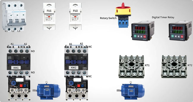
- Three-phase induction motors: 2 units
- Three-pole circuit breaker: 1 unit, for power circuit protection
- Fuses: 2 units (FU1 and FU2), for control circuit protection
- Rotary switch: 1 unit, for manual control
- AC contactors: 2 units (KM1 and KM2), for motor switching
- Thermal overload relays: 2 units, for motor overload protection
- Timer relays: 2 units (KT1 and KT2), for setting the alternating operating intervals
II. Power Circuit Wiring
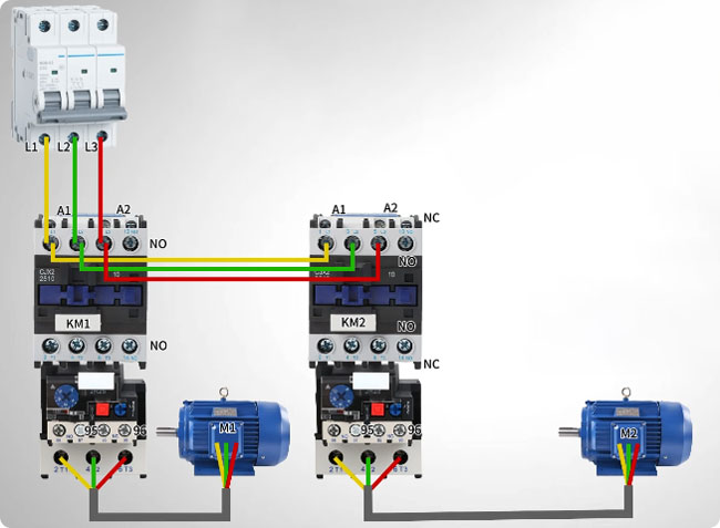
- Connect the three-phase power supply through the circuit breaker to the main contacts of contactor KM1. Route the output through its thermal overload relay to Motor 1.
- Connect the same power supply to contactor KM2, then route its output through the corresponding overload relay to Motor 2. Each contactor controls its respective motor independently.
III. Control Circuit Wiring
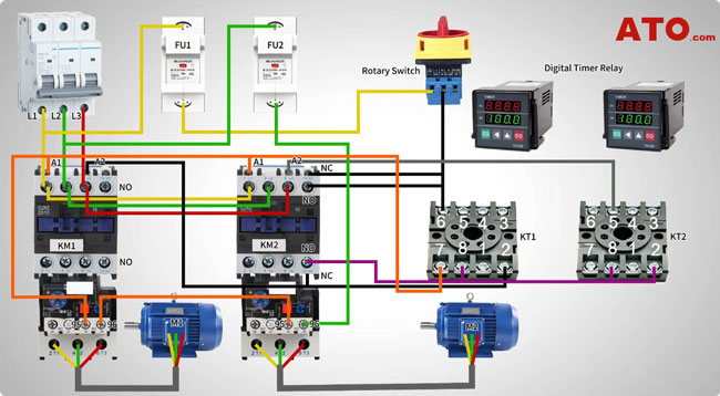
Follow the control circuit connections below, checking each terminal against the wiring diagram for the specific components.
- Step 1: Connect the control input. Connect phase L1 through fuse FU1 to the rotary switch. From the switch output, connect to the relevant normally open (NO) and normally closed (NC) contacts of KM2. Connect the NO contact to terminal 8 of timer KT1, and connect the switch output to terminal 6 of KT1.
- Step 2: Connect the KM1 control path. Connect the NC contact of KM2 to terminal 2 of KT1. Jumper this connection to coil terminal A2 of KM1 to establish the specified control path for Motor 1.
- Step 3: Interconnect the timer relays. Link terminal 8 of KT1 to terminals 8 and 2 of KT2. Connect terminal 5 of KT2 to coil terminal A2 of KM2 so that KT2 participates in controlling Motor 2.
- Step 4: Complete the return path. Connect phase L2 through fuse FU2 to terminal 96 of the KM2 overload relay. Connect terminal 95 of KM2 to terminal 96 of the KM1 overload relay. Then connect terminal 95 of KM1 to the A1 terminals of both contactor coils.
- Step 5: Connect the timer terminals. Connect the A1 coil connections in parallel to terminal 7 of both timer relays, following the specified circuit diagram.
Wiring note: Timer terminal assignments and contact states vary by model. Before energizing the circuit, verify the timer contact diagrams, coil voltage, overload relay connections, and the complete control sequence. The connections above describe the stated wiring arrangement and should not replace a verified schematic.
IV. How the Alternating Control Circuit Works
The circuit operates in three stages:
- Initial operation: Turning on the rotary switch starts the control sequence. KM1 energizes Motor 1, while KT1 begins timing.
- Motor changeover: When KT1 reaches its preset interval, its contacts change state, initiating the transition from KM1 to KM2. Motor 1 stops, and Motor 2 starts if the control circuit and interlocks permit.
- Cycle repetition: When KT2 reaches its preset interval, its contacts initiate the next changeover. The circuit returns to Motor 1, and the alternating sequence continues.
The contactors switch the motors, the timer relays determine the operating intervals, and the thermal overload relays protect against motor overloads. Appropriate electrical interlocking is necessary to prevent both motors from running simultaneously when only one motor is intended to operate at a time.
V. Conclusion
A two-timer control circuit automates alternating operation between two three-phase induction motors, helping balance runtime in pump systems and other industrial applications. At ATO.com, we share practical technical guides to support industrial automation knowledge and applications. Before commissioning, verify the timer logic, contactor interlocking, and overload protection against the circuit schematic.
