How to Wire AC Gear Motor (Torque Motor with Gearbox)?
Generally, AC torque motors adopt cage rotor structures and increase the pole logarithm to get the low speed. They mainly operate in high load, low speed state, and can also run in stalled state in a short or long term. In this working environment, the motors provide a stable torque and also reverse torque (brake torque) to the load. The shaft of the torque motors output power not at a constant power but at a constant torque.
A speed reducer (gearbox) is a component consisting of gear drive, worm drive, and a gear-worm drive which are enclosed in a rigid housing. It is usually used as a gearing between the driving link and working machine. As it plays a great role in matching revolution speed and transmitting torque between driving machine and work machine/actuator, speed reducer is widely used in modern machinery.
ATO AC gear motor is composed of a single phase AC torque motor and a gearbox, which has high starting torque and sloping characteristics, allowing speed control simply by changing the voltage of the power supply. The special rotor provides excellent performance for holding, winding, andtensioning applications. Next, we will introduce how to wire and test a ATO AC torque motor with gearbox?
 AC torque motor specifications
The specifications of the torque motor used for testing are as follows:
- Rated Power:6W
- Frequency: 50Hz
- Rated Voltage: 220V AC
- Rated Speed: 1250 rpm
- Gear Ratio of the Gearbox: 15:1
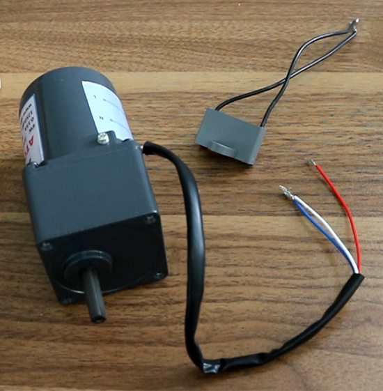
- If you purchase this 6W gear motor, a capacitor of 0.8μF is attached.
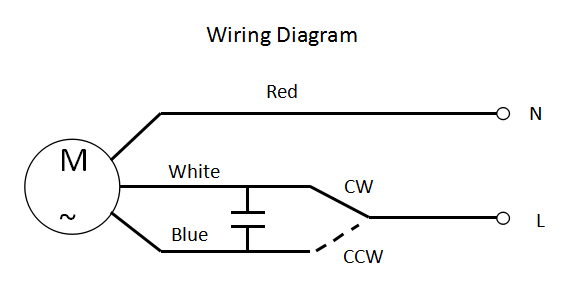
Gearbox has three wires, a red wire, a blue wire and a white wire, and the capacitor will be connected to the blue wire and the white wire. Besides, A 250V 15A switch is required to switch the direction of rotation of the motor. Once everything is ready, we can wire it according to the circuit diagram.
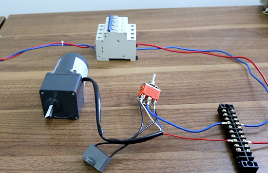
Wiring procedure
- Connect the capacitor to both ends of the blue and white lines and connect to the transfer switch.
- The intermediate terminal of the transfer switch is connected to the power supply.
- Connect the power cord and the wiring is completed.
Power on and testing
- Toggle the switch to the left and the motor rotates clockwise.
- Toggle the switch to the right, the motor rotates counterclockwise.
For more detailed wiring operation please see video below. Further more, ATO offers 3W, 10W, 20W... AC gear motors (torque motor with gearbox) for your applications as well.
