PLC-Controlled BLDC Systems: Integration & Safety
—— A Case Study on 3800W (5HP) BLDC Motors and PLC Integration
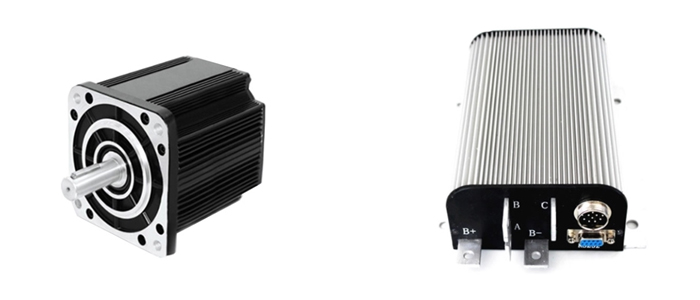
In modern automation, high-power Brushless DC (BLDC) motors are increasingly replacing traditional induction motors due to their superior efficiency and compact power density. However, integrating these systems—specifically the 3800W BLDC + Right Angle Gearbox configuration—requires careful attention to control logic, thermal management, and safety protocols.
Control Logic: Interfacing with Industrial PLCs
When integrating a BLDC controller (such as the ATO-BLDC-KBL) with a Mitsubishi PLC, the interface strategy is paramount:
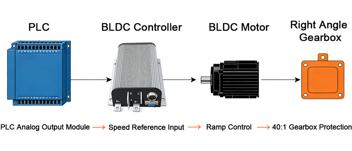
- Speed Reference: Most high-performance BLDC controllers utilize a 0-5V analog signal. In a professional setup, the PLC’s Analog Output module replaces the manual potentiometer, allowing the software to dictate precise RPM setpoints (SV).
- Ramp Control (Acc/Dec): To protect the 40:1 gearbox from torque spikes, "Ramp Control" is essential. While the controller features internal ramp settings, engineers often implement a secondary ramp within the PLC logic to ensure a smooth transition between digital run commands and target speeds.
The "Fail-Safe" Requirement: Electromagnetic Brakes
Safety is non-negotiable in industrial environments. There are two primary types of braking logic:
- Energize-to-Apply: The brake engages only when power is supplied. (Not recommended for safety-critical tasks).
- Energize-to-Release (Fail-Safe): This is the industry standard for safety. The brake is mechanically engaged by high-tension springs. It requires power to "release" the friction discs.
Integration Tip: For a true Fail-Safe system, the brake should be wired such that if the PLC signal drops to 0V or the emergency stop is triggered, the brake engages instantly to hold the load.
Thermal Management and Power Derating
Electronic components and motor windings experience increased resistance and reduced efficiency at high ambient temperatures.
The Oversizing Strategy: In a 5 hp (3.8kW) BLDC motor system, selecting a 4.1 kW-rated drive or brushless DC motor controller is a common and widely accepted engineering practice known as power derating or oversizing strategy.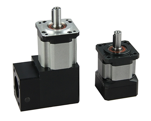
The core idea is to operate the system below its maximum rated capacity. This approach helps to:
- Reduce internal heat generation in the drive
- Lower thermal and electrical stress on components
- Improve overall system stability and reliability
- Significantly increase Mean Time Between Failures (MTBF)
Mechanical Synergy: Right-Angle Transmission
The use of a 40:1 right-angle gearbox provides high torque multiplication while maintaining a compact footprint. For seamless integration:
- Alignment: Ensure that the PLC-controlled ramp-up speed accounts for the reflected inertia through the 40:1 ratio.
- Maintenance: Always verify the duty cycle of the brake when used in high-frequency start-stop cycles to prevent glazing of the friction surfaces.
Conclusion
Successful BLDC integration is defined by the synergy between electrical control and mechanical protection. By prioritizing fail-safe braking, utilizing PLC analog setpoints for speed, and accounting for thermal overhead, engineers can ensure a robust and reliable automation solution.
