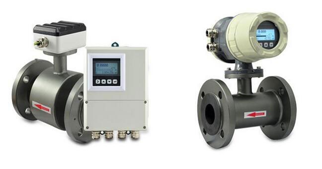
A magnetic flow meter, mag meter, or electromagnetic flow meter is a kind of instrument which measures the volume flow rate of the conductive fluid based on the principle of Faraday's Law of Electromagnetic Induction. With a large measurable flow range, the ratio of the maximum flow rate to the minimum flow rate maintains above 20:1. The mag flow meter is suitable for wide range of industrial pipe diameter, and the maximum can reach up to 3m. The output signal and the measured flow are linear, and the magnetic flow meter has high measurement precision. It can effectively measure the flow rate of fluids with a conductivity more than 5μs/cm, such as acid solution, alkaline solution, saline solution, water, sewage, corrosive liquid, mud, ore pulp, and paper pulp. Nevertheless, the electromagnetic flow meter cannot be used to measure the flow of gases, steam and purified water.
Blog
The AC contactor has found wide applications in the motor-controlled circuit. It is no exaggeration to say that the electric drive of most motors cannot be separated from the control of the AC contactor. Many electricians are very familiar with the AC contactor for their frequency use or maintenance of it. How should we calculate the AC contactor rating for the motor or other equipment and make a right choice? Let us take a look at it.
The instrument transformers like current transformer and potential transformer (also called voltage transformer) are both used for measuring devices, which have a similar working principle to transformers. The current transformer can reduce the high current to low current, while the potential transformer steps down the high voltage to low voltage for measuring the circuit or in the power distribution. They both separate the measurement circuit from the high-voltage grid to protect safety of the personnel.
In normal inspection and maintenance of pressure transducer, zero calibration and periodical blowdown of the pressure transducer would involve the starting and stopping operations. So correctly start and stop the pressure transducer is also one of the required skills. This paper describes the specific start and stop operating steps of pressure transducer.
ATO Industrial fanless embedded computers are available in a wide variety of designs and sizes, offer a high level of performance and low level of power consumption. Used for data computing, remote monitoring, and the integration of hardware and software technologies, industrial PC's are ideal computing solutions for tight spaces because they are designed with small footprints and multiple I/Os.
Combustible gas has certain characteristics of diffusion. In order to prevent the accidents caused by combustible gas leakage, the key lies in effectively controlling its continuous diffusion. Moreover, flammable gases will spread quickly driven by external forces. As a result, burning and explosion will take place. How to prevent the occurrence of this kind of accidents? What we need to do is often detecting the concentration of combustible gas whether it exceed the standard. Once the concentration exceeds the standard, give an alarm quickly and we take actions immediately. Here combustible gas detector plays an important role.
A combustible gas detector is a detector that monitor the concentration of single or multiple combustible gases and give an alarm. Combustible gas detectors are mainly divided into two types, catalytic type and infrared optical type base on the working principle.
Relays and transistors have a similar basic function, that is, both play roles of electronic switches. However, relays and transistors are very different from each other. Now let’s take a quick peek at the differences between relays and transistors.
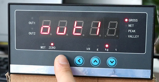
ATO 5 Digit Display Controller offers simple calibration and configuration with options for additional outputs such as 4-20 mA/ 0-10 V analogue outputs and communications ports for connection to PC's, PLC's printers and remote displays . It is designed for cooperating with load cells, force sensors and weighing sensors.
Modern industrial sensors are vastly different in principle and structure, and there are so many different types of products on the market. How can we find the ideal sensor for a specific application? When the sensor is selected, the corresponding measurement method and measuring equipment can be determined. The success or failure of measurement results largely depends on whether the selection of sensors is reasonable.
Q: What is a transformer?
A: A transformer is a device that step up or step down the voltage in an AC circuit. It converts the voltage of any value into the voltage value we need at the same frequency to meet the requirements for the delivery, distribution and use of electrical energy. For example, the electricity generated by the power plant has a low voltage level, and the voltage must be raised to be transported to a remote power consumption area. And the power supply area must be turned down to a suitable voltage level to supply power equipment and daily power equipment.
ATO provides two categories of capacitors: low voltage shunt power capacitor of the self-healing type (three-phase series) and self-healing low voltage shunt capacitor (single phase, for mineral thermal oven).
Self-healing low voltage shunt power capacitors are used in 50Hz and 6oHz power system. The function of these capacitors contains: reducing reactive power loss, improving voltage quality, enlarging capacity of voltage transformer, etc.
Even though the capacitor’s price varies with its capacity, ATO self-healing three/single phase shunt power capacitors are inexpensive. Here is the price list and welcome to select the best one for you!
With the rapid development of industrial automation, the variable frequency drive, used for frequency conversion debugging, is thereof widely used. As an important role of frequency conversion speed regulation and energy saving, VFD is mainly used to control the AC motor's power control equipment by changing the frequency of the motor's working power supply. It's not only advantageous for improving the enterprise's process and production level, but also plays an important role in energy saving. But how should we choose an appropriate VFD?
The ATO 1000-50000mm draw-wire displacement sensor has a small mounting size, compact structure and high precision. Its measuring range can be 1000mm/2500mm/5000mm or even 50000mm. This draw-wire displacement sensor is particularly suitable for linear rolling guide system, hydraulic cylinder system, testing machine, telescopic system (forklift, press, lifter, pipe bender, bending machine, etc), crane or cable winch, reservoir dam protection system, gate opening control system, pressure machine, hydraulic universal experimental machinery, warehouse location position, length and displacement measurement and position control of various industrial instruments.
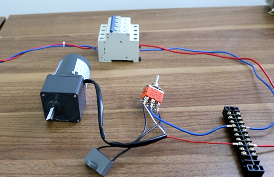
ATO AC gear motor is composed of a single phase AC torque motor and a gearbox, which has high starting torque and sloping characteristics, allowing speed control simply by changing the voltage of the power supply. The special rotor provides excellent performance for holding, winding, andtensioning applications. Next, we will introduce how to wire and test a ATO AC torque motor with gearbox?
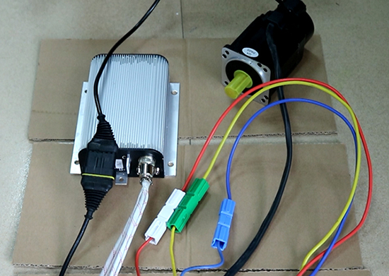
Generally, the wiring principle of brushless DC motor is basically similar. Next, we choose the model ATO-BLDC-40030 of ATO high torque BLDC motor and its matching controller ATO-BLDC-TH-G as examples to show you how to connect the motor to the controller and make the motor rotate.
A gas detector or gas monitor is a device to detect the concentration of a gas in one area. It is widely used to monitor the leakage of gas and give an alarm to ensure the safety of life and production. ATO offers a series of gas detectors to monitor the leakage of ammonia, carbon monoxide, hydrogen sulfide, chlorine, hydrogen etc. There are two types - portable and fixed - for different requirements of applications. In addition, the portable gas detectors are available for diffusion-type and pump-type. Here is listed some features and prices of ATO gas detectors for your reference.
ATO gas detector features
- Adopt high-accuracy sensor with high precise detection.
- Two-stage alarm with sound and light, and alarm point is settable.
- With display, easy to readout.
- Rugged and durable housing.
- Portable gas detectors has rechargeable lithiumpolymer battery with large capacity.
What is the frequency converter? Frequency converter outputs the AC power to pure sine wave after the transformation of AC→DC→AC, the output frequency and voltage can be adjusted within a certain range. It is different from the variable frequency drive (VFD) used for motor speed regulation, and also different from the common AC regulated power supply. An ideal AC power supply is characterized by stable frequency, stable voltage, zero internal resistance and pure sinusoidal voltage waveform (without distortion). Frequency converter is quite close to the ideal AC power supply, so more and more countries use it as standard power supply to provide the best power supply environment for electrical appliances, so as to assess the technical performance of electrical appliances.
Loop powered signal isolator is one type of signal isolator with a power supply module. The function of the loop powered signal isolator is to isolate the current source signal input to the loop powered isolator and output a DC signal that is isolated from and proportional to the input signal.
Loop powered signal isolators use the signal current in the input loop to power the meter (take out some energy of input signal inside the isolator to drive the isolator), without any external power supply.
Correct selection of the frequency converter or frequency changer is crucial for the normal operation of electronic control system for mechanical equipment. To buy the frequency converter, according to the type of mechanical equipment, load torque characteristics, speed regulation range, static speed accuracy, starting torque and the requirements of the use environment, and then choose the suitable frequency converter.
Before selecting the frequency converter (AC power supply), we should firstly make clear the input mode of load, it is three phase or single phase? Secondly, determine the load characteristics, such as resistive load, inductive load, capacitive load, mixed load. Since different load characteristics will cause different inrush currents when the load starts, the influence of inrush current must be considered when buying the frequency converter, otherwise converter will not output normally.
As a matter of fact, the main function of the series reactor is to restrain the higher harmonic or limit the switching surge, prevent the harmonic wave from endangering the capacitor, avoiding the excessive amplification and resonance generation of the access of the capacitor to the power grid harmonic. As to the increasingly automatic life, the harmonic problem of the power system is becoming increasingly serious. We have to take measures to process the harmonic, because a too high harmonic will seriously affect the normal operation of the device and electrical system.

