120v VFD setup for 1-phase/3-phase 220v motor
Thu, Nov 1, 2018
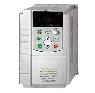
A device that converts alternating current with constant voltage and frequency into alternating current with variable voltage or frequency is called "variable frequency drive". VFD has the functions of voltage regulation, frequency modulation, voltage stabilization, speed regulation etc. VFD is generally used to control 3 phase AC motor in variable speeds. Now the three phase 220v-240v motor can run on single phase 120v power supply. ATO offers you 110v/120v input, 220v/230v/240v output VFDs. It can not only realize single phase input & output, but also convert single phase to three phase.