Pull Rope Switch Working Principle
Sat, Sep 18, 2021
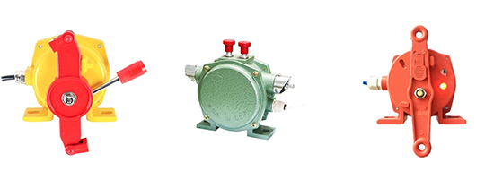
The pull rope switch is composed of pull rod, reset handle, cam, lock slot and micro switch. The pull rope switch is installed on the frame on both sides of the belt conveyor, and the switch is connected with the steel wire rope along both sides of the conveyor. When an emergency occurs in the conveyor belt equipment, the wire rope is pulled anywhere along the line at the site, and the wire rope pulls the drive arm to rotate, which drives the torque spring through the drive shaft to displace the precision cam and drive the control line, making the conveyor stop running.